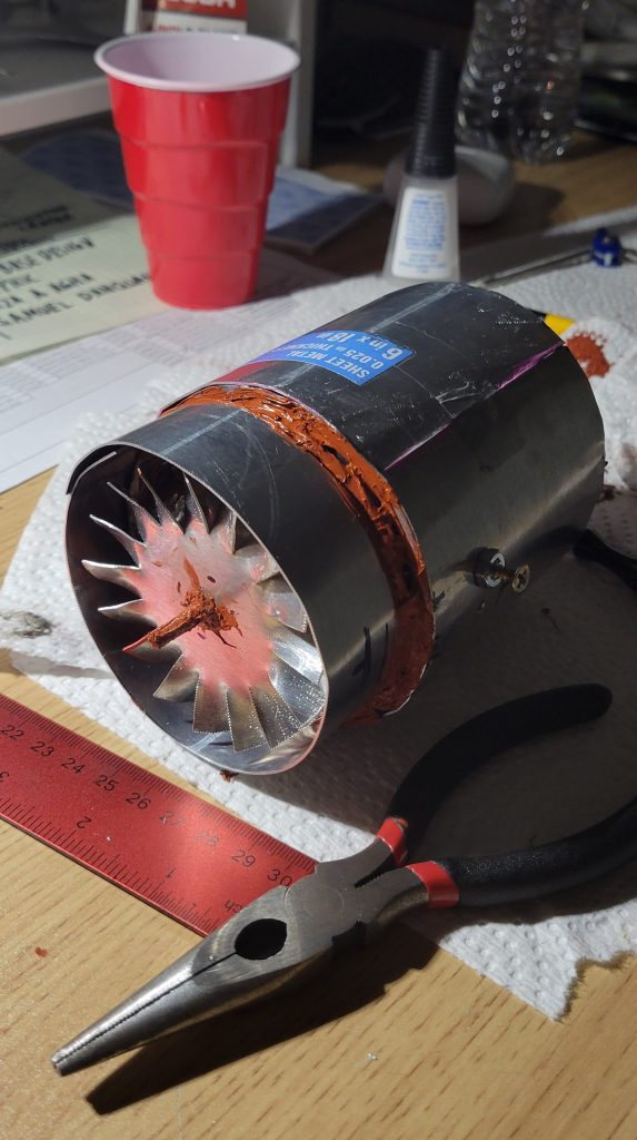
It’s always fascinated me with the idea of propelling objects with a force that isn’t completely visible, yet so powerful. After months of studying and researching propulsion, I started experimenting with home-made turbo-fan engines. I chose to begin building turbofan engines because they are rather simple and teach the basics of gas turbines. In the summer of 2024, I built my prototype turbofan engine. Regarding my resources and time, I had to find ways to scale down the engine. During the process, I researched materials, fuels, airflow, and the jet’s mechanics. After two months of research and building, the product was a lightweight aluminum, butane-powered engine. I used 1 intake fan and 2 compressor fans, which pressurized the air towards the combustion chamber.
From inspiration from actual Turbo-fan engines, I also directed a fraction of the air around the outside of the combustion chamber to improve efficiency. For testing, I attached the engine to the free-moving rack, which would indicate how much thrust the engine would produce. The engine managed to produce an estimated 1-2 pounds of thrust. However, not efficient, I found the engine fascinating and awesome as it would spit flames out the other end while increasing fuel as well as thrust. I was extremely pleased by my creation and started working on ways to improve it. I started looking for ways to make it significantly more powerful. My research led me to the turbojet engine.
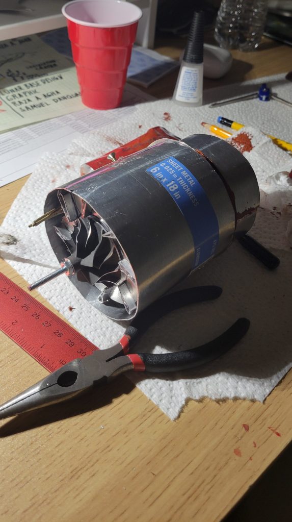
I realized that turbo-jet engines fascinate me even more because of their efficiency at high speeds, thanks to their weight-to-power ratio. Instead of directing air in 2 directions, such as the Turbofan, the Turbojet directs all of its cold air into the combustion chamber for maximum airflow and thrust. They are mostly used in smaller, lighter planes and especially fighter jets. For a small-scale build, I improvised by using car turbochargers and high melting-point aluminum, which I joined together using a high-temperature, car engine gasket silicone sealer. I spent quite some time researching materials, power sources, and CAD designs for the most efficient final product. I first researched how car engines efficiently operate during their combustion process and how it might relate to a jet engine’s combustion process. Amazingly, they have nearly the same process for combustion. Although both types of engines execute their process differently, they both follow the Otto cycle. The Otto cycle includes a step-by-step process. It follows: Intake, Compression, Combustion, and finally, Exhaust. In the turbojet’s case, the exhaust step is when the engine directs its thrust for propulsion.
However, along the way, I came across a few problems with the engine. Such as inefficient combustion and airflow. It took many trials and errors to derive solutions that could fix my problem, which required me to reverse-engineer the entire engine and experiment with new parts and ideas. My research indicated that to resolve my combustion issue, I needed to research different types of fuels and ignitors, such as propane, butane, kerosene, and combustion chamber designs. I found that the engine would perform the best when operating on kerosene. However, for my airflow issue, the solution was much simpler. The reason why there wasn’t enough oxygen reaching the combustion chambers was that I had too weak an intake. This was because my ball bearings had too much friction, causing resistance on the intake turbine. Finally, I am in the process of designing a CAD model of an inlet piece. Without the inlet piece, the turbine will be unable to compress the air. Hopefully, after successful testing on the Turbojet, I will be designing and building a remote-controlled aircraft powered by my Turbojet soon.

Leave a comment