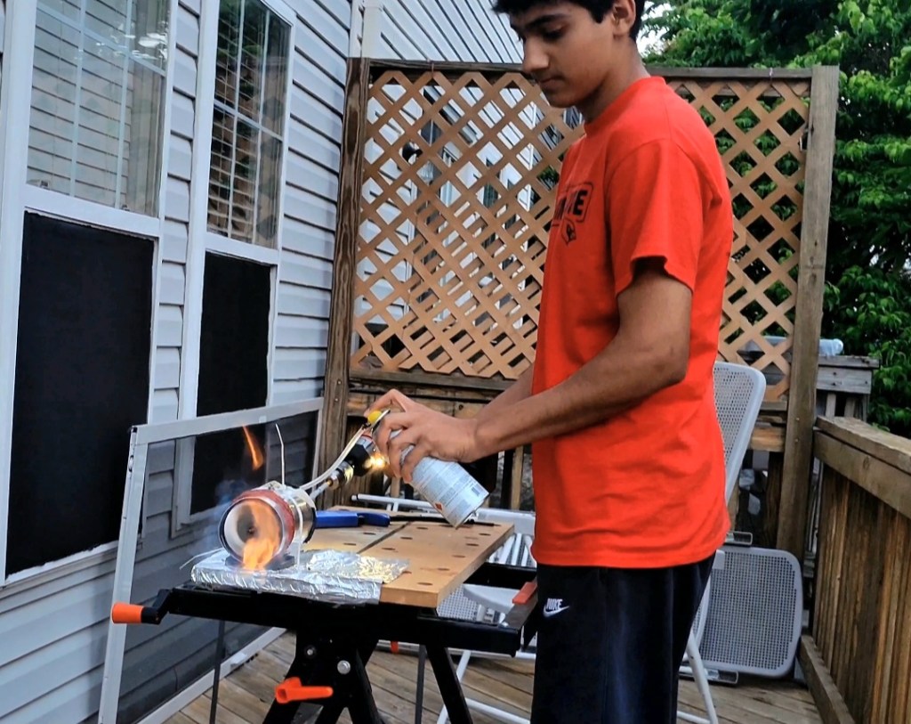
Picking up where I left off from Part 1, after finishing building the engine, it was ready for testing. I placed an aluminum sheet underneath where the engine would be seated for heat shielding against the wooden table. I strapped the engine to the table using heavy-duty zip ties to ensure the engine would not shift while testing. I now needed a high RPM motor that would attach to the turbine to create airflow and stable connection between the engine fuel lines and the Butane aerosol. I ended up using the same fuel line strategy from my first jet engine. I bunched up all my brass fuel lines and fit them into a vinyl tube, which is attached to the Butane aerosol can. Finally, I required a motor which would connect to the turbine to create airflow inside the engine. I preferably sought for a high RPM motor which would result in the strongest and most efficient form of airflow. I first decided to incorporate my own 6000 RPM Lego Turbine Motor since it would meet my needs perfectly. However, the motor lacked torque and consistency in RPMs while testing. I then looked for other forms of high RPM motors until I improvised using a drill machine which would be fitted tightly to a Lego axle. I decided to use Lego axles because this would let me attach universal joints from the drill machine to the turbine rod in the engine. The universal joints aided me because it allowed conveniency by letting me hold the drill machine in any position while operating. At last, I primed and injected the fuel and then started the turbine. At first, there would be a large flame erupting from the engine but after increasing airflow, the flame would be more direct and would transition from orange to blue. This blue flame indicated efficient combustion inside the engine which resulted in thrust. Don’t forget to turn up the volume to hear my full commentary.
Jet Engine Part 2
by
Tags:

Leave a comment